How are Engineering Drawings for Hydraulics Different from Regular Engineering Drawings?
Engineering drawings have many symbols that are standard and carry over from industry to industry. Engineering drawings for hydraulics have a few symbols and practices that distinguish them from a standard engineering drawing. The basic drawn lines, cylinder symbols, ejector symbols, and the Do Not Scale note are just a handful of items that are particular to engineering drawings for hydraulics.
What is the Do Not Scale Note?
One particularly unique thing about hydraulic drawings is that they are not drawn to scale and are not meant to be an exact replica of a hydraulic circuit. Engineering drawings for hydraulics are meant to show components and their connections. The Do Not Scale note is contained in the title block on the drawing.
What are the Basic Hydraulic Pipe Symbols?
Every engineering drawing will use drawn lines to connect components, however in hydraulic drawings those drawn lines reference connectors that carry fluid and symbolize hydraulic lines, also known as pipes. Hydraulic lines can be external, such as a pipe, or internal, as in a manifold . Hydraulic lines include working lines, tank lines, pilot lines, and drain lines.
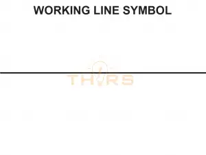
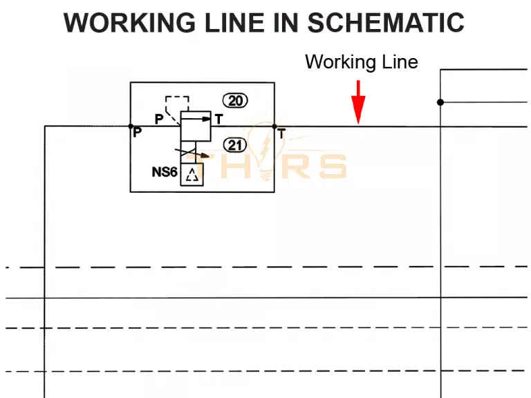
What are Working Lines?
Working lines are hydraulic pipes that carry out all the work in the hydraulic system, such as moving fluid to push a cylinder, charging an accumulator, and returning oil to the reservoir. Normally, these drawn lines are color-coded on a drawing. If the drawing is black and white, the working line, or pipe, is differentiated from other hydraulic pipes by its location within the schematic.
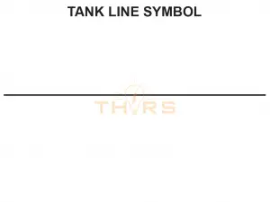
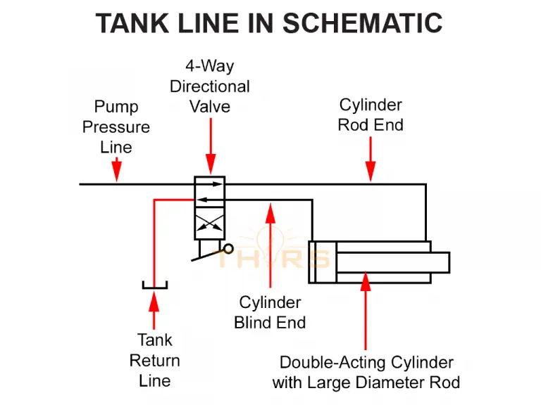
What are Tank Lines?
Tank lines are hydraulic pipes are used to return oil to the reservoir after the fluid has been out in the system. Tank lines are also often differentiated by their location on the schematic as the drawn line for them is the same as some other drawn lines for other hydraulic pipes.
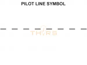
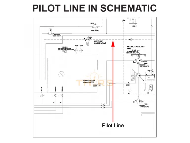
What are Pilot Lines?
Pilot lines are used in a multi-stage valve, where the small stage valve uses a pilot valve to control the large valve. The hydraulic pipe is illustrated by a dashed line.
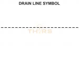
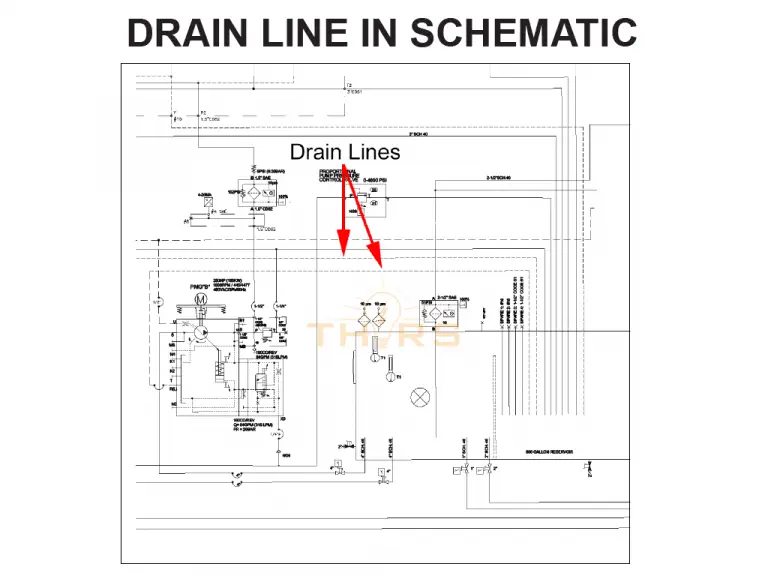
What are Drain Lines?
Drain lines are on the opposite side of the system from the pilot lines. As pilot lines are used in the valves, the excess oil from the valves goes back to the tank via the drain lines. This hydraulic pipe is illustrated with a dotted line.
What are Cylinders and Ejectors?
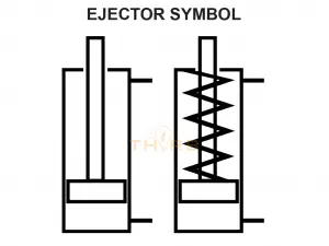
Cylinders do the major work in a hydraulic system but in a hydraulic press, an ejector is also needed. Both components utilize the same basic symbol and it’s another case of needing to know the system being worked on to differentiate between two symbols on a hydraulic drawing.
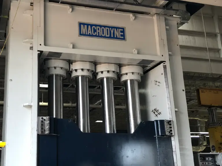
If the symbols are the same, what’s the functional difference between the two? Cylinders are mechanisms connected to the slide which help in moving the slide up and down. On the other side, the cylinders are mounted to the frame at the top of the system. Cylinders are one of the major components of the hydraulic system and are needed to build a hydraulic press.
Courtesy of Macrodyne Technologies Inc.
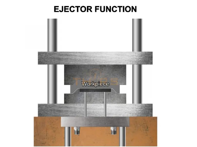
Ejectors, on the other hand, are the component of the machine that ejects the created part out of the tool. Such press-specific cylinders can be defined as an auxiliary circuit attached to the main press circuit consisting of an upper ejector and a lower ejector.
Here is the symbol that is used for both an ejector and a cylinder:
There are a few other symbols that will mark out an engineering drawing as a hydraulic circuit, but the line symbols, cylinder symbols, ejector symbols, and Do Not Scale note are obvious, easy things to pick out immediately.
Every manufacturing company that uses drawings to develop a manufacturing plan and estimate the production time might calculate product costs incorrectly if there are errors in those…
Due to the complex nature of the geometric dimensioning and tolerancing (GD&T) standard, a company’s bottom line profitability can be affected as a result of reading and interpreting…
Geometric dimensioning and tolerancing is a complicated and complex standard that can lead to reading and interpreting errors. On drawings, GD&T is used as a…