
Training
Training Programs are Critical to Attracting and Retaining Talent
In today’s rapidly changing business landscape, organizations face a unique set of challenges in finding, hiring, and retaining top talent. The tight labor market has

Career Planning
How THORS Courses Helped a Mechatronics Student in Germany
Sasshank is an international student attending University in Germany where he studies mechatronics engineering. He was born in Tamil Nadu, where he attended various schools

Training
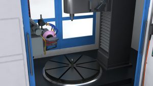
The Role of Virtual Reality in Technical Training
In the rapidly evolving landscape of technology and industry, virtual reality (VR) in technical training is leading a revolutionary transformation in how professionals are trained.