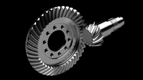
Tooth contact pattern testing is an important inspection process used to verify proper tooth engagement, load distribution, and alignment in bevel gear systems. A proper tooth contact pattern is essential for smooth gear meshing, balanced load distribution, reduced vibration, and longer gear service life. An improper tooth contact pattern can create excessive stress concentrations, uneven meshing, surface fatigue, noise, and premature gear failure. Because even small alignment or setup errors can significantly affect gear performance, bevel gear tooth contact pattern testing must be performed carefully and accurately under proper operating conditions.
The following are 5 best practices that help improve the accuracy and reliability of bevel gear contact pattern testing.
1. Test Under Simulated Operating Load
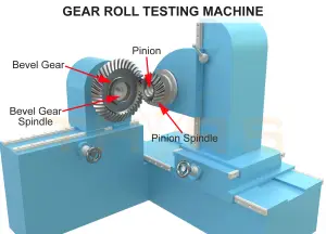
One of the most common mistakes in bevel gear tooth contact pattern testing is checking the pattern under no-load conditions. In actual operating environments, gear teeth deflect slightly as torque increases. This deflection causes the contact pattern to shift from its original unloaded position. For this reason, testing should always be performed under simulated operating load to identify the true contact behavior of the gear set. A contact pattern that appears slightly off-center during setup may move into the correct position once load is applied. Without simulated loading, technicians may incorrectly reject properly manufactured gears or overlook alignment issues that only appear during operation. As a result, testing under realistic load conditions helps ensure accurate gear alignment, proper load distribution, and long-term gearbox reliability.
2. Use the Correct Application Method for Marking Compound
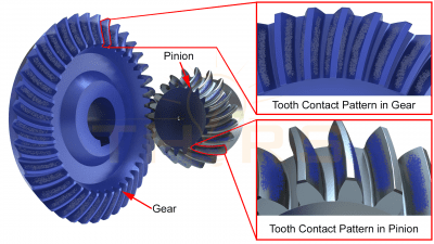
The marking compound used during bevel gear contact pattern testing plays a major role in pattern visibility and interpretation accuracy. Applying the marking compound incorrectly can create misleading impressions that result in unnecessary adjustments or incorrect setup decisions. In practice, a thin and uniform layer of marking compound is applied to the gear, pinion, or sometimes both to produce a visible contact pattern on the tooth flanks. Excessive compound thickness often creates artificially large contact areas. Similarly, uneven application can make the pattern difficult to interpret. Many technicians use a small roller or applicator to maintain a consistent film thickness across the tooth surface and improve pattern clarity. The gear teeth must also be cleaned thoroughly before every test because leftover compound from previous inspections can distort the new pattern.

3. Evaluate Tooth Contact Pattern Position, Size, and Shape
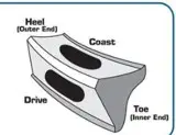
Evaluating a tooth contact pattern goes beyond simply checking whether the contact area is centered on the tooth surface. The position, size, and overall shape of the pattern must all be evaluated together to determine whether the gears are aligned correctly. Ideally, the contact area should be centered between the heel and toe while remaining slightly away from the tooth edges, top land, and root area. The pattern should also cover a moderate portion of the tooth surface, since extremely small patterns may indicate concentrated loading. In contrast, poorly shaped, skewed, or broken contact patterns may indicate alignment errors, runout, mounting inaccuracies, or surface defects that can eventually lead to noise, overheating, and premature wear.
4. Check Both Drive and Coast Flanks
Every bevel gear tooth contains two working surfaces known as the drive flank and the coast flank. The drive flank carries load during normal power transmission, while the coast flank becomes active during reverse rotation or deceleration conditions. Many inspections focus only on the drive side, but examining the coast side is equally important because certain alignment and backlash problems appear more clearly on that surface. Uneven coast-side contact patterns can contribute to vibration, noise, and poor gear performance during reversing or braking conditions. During tooth contact pattern testing, the gear set must be rotated in both directions so that the resulting pattern can be observed separately on both the coast and drive flanks.
5. Document Results and Establish Inspection Standards
Consistent documentation is an essential part of effective bevel gear tooth contact pattern testing because it improves troubleshooting accuracy and setup repeatability over time. Specifically, important inspection data such as contact pattern photographs, backlash measurements, mounting distances, and load conditions should always be recorded during testing. In addition, maintaining detailed records allows technicians to compare current inspections with previous setups. This makes it easier to identify wear trends or recurring alignment issues more efficiently. Inspection standards should also be established in advance using OEM recommendations, AGMA guidelines, ISO standards, and historical operating data from similar gear systems.
By following these best practices, technicians can improve inspection accuracy, reduce setup errors, and detect potential gear issues before they lead to premature failure. This ultimately helps industries maintain reliable gearbox performance, minimize downtime, and ensure consistent power transmission under demanding operating conditions.
Want to see these best practices applied under real meshing conditions? Explore our course on bevel gear composite measurements for a deeper look at how contact patterns are evaluated and interpreted in practice.
Looking to broaden your gear inspection skills? Our course on elemental measurements for cylindrical gears covers the methods used to assess dimensional accuracy, functional performance, and reliability.