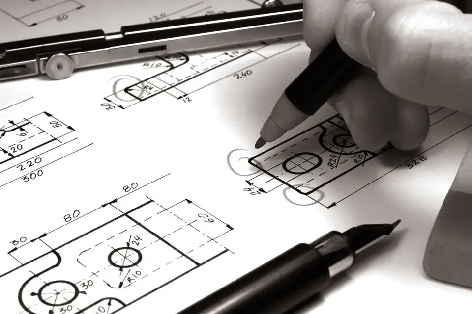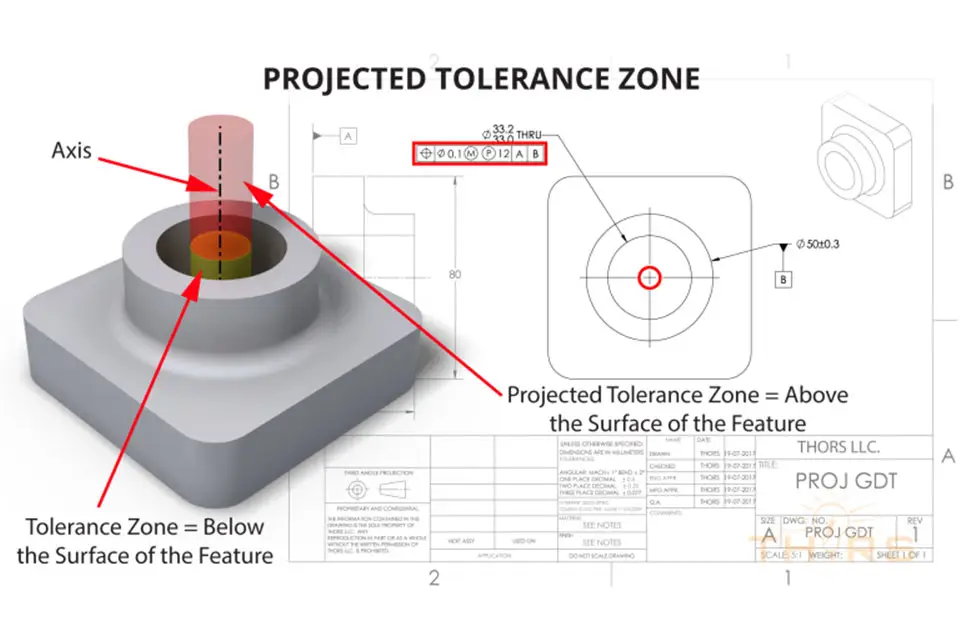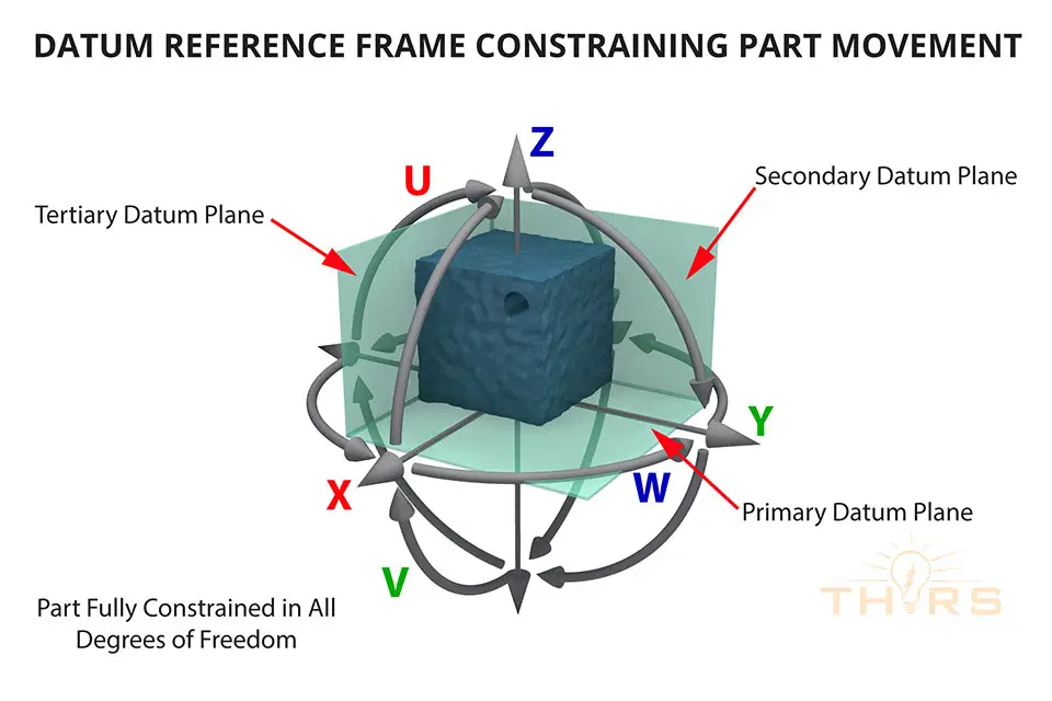
Engineering drawings are the single source of truth for wiring harness design and assembly. They turn electrical ideas into parts that can be built, tested, and repeated. This article examines why these drawings matter and what information they contain. It also traces how they influence every stage of a harness’s lifecycle, from the initial design sketch to the final quality check on the assembly line.
What Makes Wiring Harness Drawings Different?
Most engineering drawings show geometry, the shape and size of a part, while wiring harness drawings describe something more complex: a network. A harness has wires, connectors, terminals, splices, and protective coverings. Each part must connect at a specific point, in a specific way. The whole harness must also fit into a specific physical shape, without touching other parts nearby.
Because a harness is a network, not just a shape, its drawing has to capture more than geometry. That information typically lives in one document, or across a set of drawings:
- Point-to-point wiring information, such as which wire connects to which terminal on each connector at each end
- Physical routing and form board layout, including the actual path the harness takes, bend points, branch-outs, and lengths
- Component and material callouts, including connector part numbers, terminal types, wire gauge, insulation color, and protective materials like conduit or tape
- Assembly instructions, including crimping specifications, splice methods, and torque values where applicable
- Test and inspection requirements, such as continuity checks, pull-test values, and dielectric requirements, which measure how well the insulation resists electrical breakdown
No single drawing can show all of this. That’s why harness documentation usually includes a schematic, a wire run list sheet, and a full-scale layout drawing that work together.
The Schematic: Defining the Electrical Intent
The schematic is where the harness begins its life. It shows the electrical connections between components, regardless of where those components sit physically. For example, it shows which switch connects to which relay. It shows where a sensor is grounded. It shows which circuit a given fuse protects. Engineers and Subject Matter Experts (SMEs) use the schematic to check that the electrical design works, before a single wire is cut.
Because the schematic ignores physical layout, it’s the best place to catch logic errors, such as a missing ground path, a fuse rated wrong for the circuit, or a circuit that draws more current than its wire gauge can safely carry. Fixing these problems here is far cheaper than fixing them after harnesses are built.
The Wire Run List Sheet: The Bridge Between Concept and Component
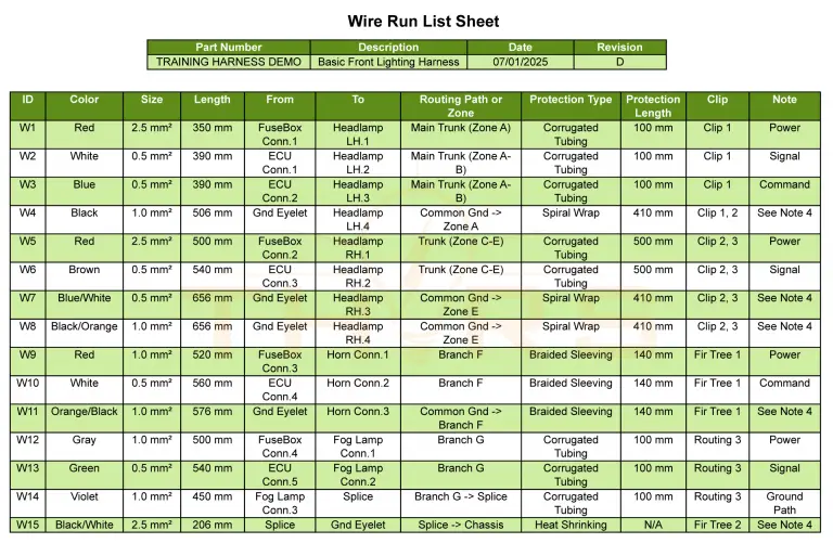
Once engineers validate the schematic, they convert the electrical intent into a buildable specification. It assigns real-world details to each wire, including gauge, color, length, terminal type at each end, and the exact connector cavity it plugs into.
At this point, drawings start to drive procurement and assembly decisions. A wire list tells buyers what to order. It tells assemblers exactly which wire goes where, down to the cavity number. Ambiguity here is costly. One wrong cavity assignment could make a sensor read the wrong signal, or worse, short two circuits together.
The Layout Drawing: Giving the Harness a Physical Form
The layout drawing, or form board drawing, is the most recognizable type of harness document. It shows the harness at full scale, exactly as it will be built on a pegboard or form board fixture. It calls out branch lengths, bend locations, tape wrap zones, connector orientations, and protective sleeving.
Why Precision Matters in Wiring Harness Design and Assembly
Wiring harnesses are usually assembled by hand, or with semi-automated equipment that handles part of the process while people do the rest, often at high volume. Assemblers rely entirely on the drawing to know what to do. They don’t see the broader system design. So, drawing accuracy directly affects build quality.
There are a few consequences of imprecise or outdated harness drawings:
- Rework and scrap: A wrong wire gauge or connector callout can make an entire built harness unusable.
- Field failures: Routing that was never checked against real component clearances can cause chafing and shorts once the product is in service.
- Traceability gaps: Revision control is a record of which drawing version is current and what changed. Without it, teams can’t easily tell which harness configuration shipped in which unit, which complicates recalls and field fixes.
- Cost overruns: An engineering change order found late in production costs far more to fix than the same issue caught during drawing review. As a result, harness drawings almost always go through formal revision control and cross-functional review, with sign-off from engineering, quality, and manufacturing, before release.
Standards and Conventions That Keep Drawings Universal
Wiring harness drawings follow set conventions. That way, anyone trained to read them, whether a design engineer, a buyer, or a line assembler, interprets them the same way. Wire color codes, connector symbols, gauge notations, and reference designators all follow industry or company standards. In addition, many industries add their own rules on top. For example, automotive harness drawings often follow standards set by the Original Equipment Manufacturer (OEM), the company selling the finished vehicle. Aerospace harnesses must meet strict documentation rules tied to certification and safety.
This standardization is part of what makes engineering drawings for wiring harness design so powerful. They aren’t just internal reference documents; they’re a shared language. Harness design, sourcing, manufacturing, and quality control can all work from the same information, even across different companies or countries.
From Drawing to Assembly Line
On the shop floor, the layout drawing is often reproduced to scale and mounted on a form board, a fixture with pegs marking every bend and branch point. Assemblers lay wires directly onto the board, following the drawing. Then they add connectors, terminals, and protective coverings exactly as specified. Finally, quality inspectors check the finished harness against the drawing, confirming wire routing, terminal crimps, and continuity.
In more automated environments, the drawing data feeds directly into cutting and crimping machines. It also feeds automated test systems, which verify every circuit against the wire list before shipping. Either way, the drawing stays the single reference for assembly, inspection, and testing.
Engineering drawings are essential to wiring harness design and assembly. They carry electrical logic from the schematic, material and connection details from the wire list, and physical form from the layout drawing. Together, these become a set of documents that manufacturing teams can use, again and again, to build harnesses reliably. As electric vehicles, advanced driver assistance systems, and denser electronics make wiring harnesses more complex, the discipline behind these drawings matters more, not less. Precise, well-controlled engineering drawings are more than paperwork. They make sure a harness is safe, repeatable, and fit for the system it powers. Want to learn more about engineering drawings for electrical circuits? The THORS Engineering Drawing for Wiring Harnesses course is a good place to start.