In electronics, power converters are devices that transform an input signal from one state or voltage level to another, enabling efficient energy transfer and utilization. This conversion provides the required current or voltage to meet specific application needs. Typically, a power converter requires power semiconductor devices and control circuits to perform the conversion process.
An important aspect of power conversion is electrical signal conditioning, which involves filtering noise to produce a clean and stable output signal. The main types of power converters include AC to DC converters, DC to AC converters, AC to AC converters, and DC to DC converters.
What is an AC to DC Converter?
An AC to DC converter, also known as a rectifier, is an active electronic circuit that converts an AC input voltage into a DC output voltage using diodes. AC to DC converters are most commonly found in consumer electronic devices such as televisions, computer systems, and battery chargers.
Components of an AC to DC Converter Circuit
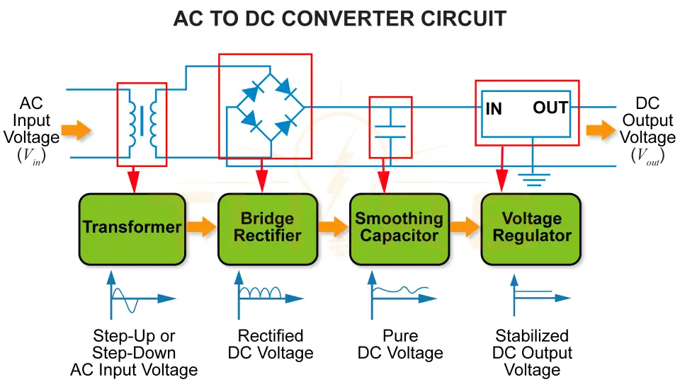
An AC to DC converter circuit is built using a transformer, a bridge rectifier, a smoothing capacitor, and a voltage regulator.
Transformer
- Used to step up or step down the input AC voltage depending on the requirement
- Composed of four diodes
- Converts the AC input voltage to rectified DC voltage
Smoothing Capacitor
- Filters the rectified DC voltage
- Helps produce a smoother and more consistent DC voltage by reducing ripple
- Maintains a stable DC output voltage
- Ensures consistent voltage despite fluctuations in the circuit
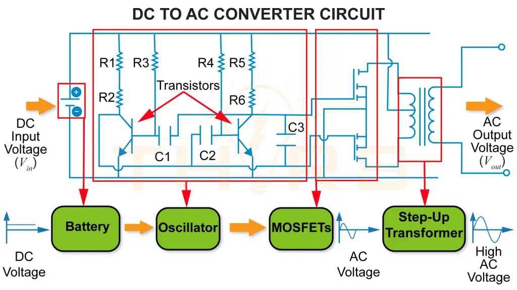
What is a DC to AC converter?
A DC to AC converter, also known as an inverter, is an active electronic circuit that converts a DC input voltage into an AC output voltage. DC to AC converters are commonly used in car power outlets, solar power systems , and Uninterruptible Power Supply (UPS) devices.
Components of a DC to AC Converter Circuit
A DC to AC converter circuit is built using an oscillator, Metal Oxide Semiconductor Field Effect Transistors (MOSFETs), and a step-up transformer.
- Interrupts the DC input voltage from the battery at periodic intervals
- Converts steady DC into a pulsed signal to mimic AC
MOSFETs
- Act as electronic switches controlled by the oscillator
- Help generate alternating current from the pulsed DC
Step-up Transformer
- Increases the resulting AC voltage to a higher level
- Delivers high AC voltage as the output
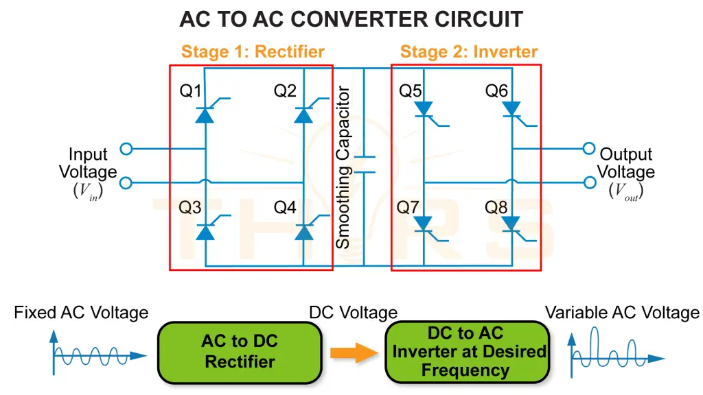
What is an AC to AC converter?
An AC to AC converter, also known as a voltage regulator, is an active electronic circuit that converts a fixed AC voltage to a variable AC voltage, or a variable AC voltage to a fixed AC voltage. These converters are commonly used in speed control systems and applications that require a variable voltage levels.
A back-to-back converter is an example of an AC to AC converter.
Components of Back-to-Back Converter Circuit
A back-to-back converter circuit consists of a rectifier and an inverter connected in series. It typically uses eight Insulated Gate Bipolar Transistors (IGBTs) with freewheeling diode pairs that act as switching devices.
Stage 1: Rectifier
- Converts the input AC voltage into DC
- Filters out ripple with a smoothing capacitor to produce a smoother output
Stage 2: Inverter
- Converts the DC voltage back into AC
- Alters the frequency to convery fixed AC voltage to variable AC voltage, or vice versa
What is a DC to DC converter?
A DC to DC converter, also known as a chopper, is an active electronic circuit that changes the voltage level of a DC source to the required output level. The variation in output depends on the duty cycle, which is the ratio of the time the switch is ON during each cycle to the total cycle time.
If the duty cycle is less than 0.5, the DC to DC converter operates in buck mode to step down the output voltage. If the duty cycle is greater than 0.5, the converter operates in boost mode to step up the output voltage.
Components of a DC to DC Converter Circuit
A DC to DC converter circuit consists of a semiconductor switch, typically a MOSFET, an inductor, a capacitor, and a freewheeling diode.
Semiconductor Switch
- Turns current flow ON and OFF rapidly to control energy transfer
- Regulates the duty cycle, which determines the output voltage
Inductor
- Stores energy when the semiconductor switch is ON
- Releases stored energy to the load when the semiconductor switch is OFF
Capacitor
- Filters and smooths the output voltage by reducing ripple
- Acts as a temporary energy reservoir to supply current to the load freewheeling diode
- Provides a current path when the switch is OFF
- Allows the inductor and capacitor to discharge safely
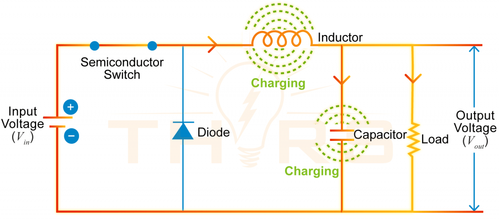
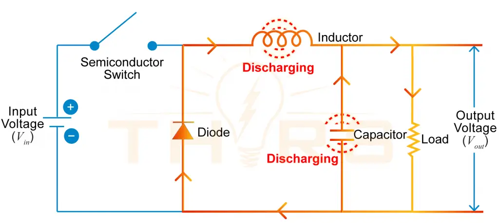
A diagram of a buck-type DC to DC power converter circuit showing the direction of current flow during the semiconductor switch ON and OFF states.
Whether converting AC to DC, DC to AC, AC to AC, or regulating DC voltage levels, power converters play a vital role in ensuring stable and reliable power delivery. In addition to power converters, many other active electronic circuits are used across a wide range of modern electronic applications.
For those looking to build a solid foundation in this area, the THORS Active Electronic Circuit Basics course offers a comprehensive introduction to commonly used circuits built with active components and serves as an excellent starting point for students and professionals alike.