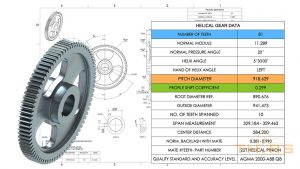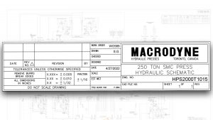

Engineering Drawings
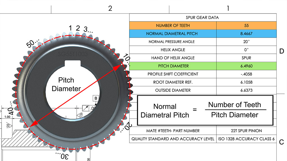
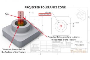
Beyond Symbols: Fluency in GD&T Decreases Cost
Due to the complex nature of the geometric dimensioning and tolerancing (GD&T) standard, a company’s bottom line profitability can be affected as a result of reading and interpreting

Training
Upskilling in the Manufacturing Industry with THORS
In today’s rapidly evolving manufacturing industry, staying up to date with the latest technologies and processes is crucial to remaining competitive. Upskilling in the manufacturing industry

Training
Certificate Programs vs Completion Certificates
Certificate programs and completion certificates are both types of educational programs that can provide valuable training and skills to individuals in a variety of fields.