PLC Ladder Diagram (LD) is one of the most widely used programming languages in PLC programming. The term PLC Ladder Diagram, or Ladder Diagram, refers to the graphical programming language defined in the IEC 61131-3 standard for programmable logic controllers.
Industries prefer this ladder logic language because it offers simplicity, clarity, and a strong connection to traditional electrical control circuits. These characteristics make it highly effective for industrial automation applications.
Why PLC Ladder Diagram Is Easy to Understand and Learn
A ladder diagram is designed to look like traditional relay-based electrical control circuits. Because of its familiar structure, electricians, technicians, and engineers can understand the logic without requiring advanced software programming knowledge.
The symbols used, such as contacts, coils, timers, and counters, are intuitive and widely recognized. This makes PLC Ladder Diagram ideal for beginners and for teams with mixed technical backgrounds.
A Ladder Diagram Makes Troubleshooting and Maintenance Simple
One of the biggest advantages of a ladder diagram is how easy it is to troubleshoot. PLC software allows real-time monitoring, where energized contacts and outputs are highlighted during operation.
Maintenance engineers can quickly:
- Identify faulty inputs or outputs
- Track logic flow rung by rung
- Fix issues without stopping the entire system
This reduces downtime and improves system reliability.
Strong Industry Acceptance of PLC Ladder Diagram
PLC Ladder Diagram is widely used across industries such as:
- Manufacturing
- Automotive
- Food and beverage
- Water treatment
- Power generation
Most PLC platforms support Ladder Diagram programming, making applications portable and standardized across vendors. Its widespread use makes Ladder Diagram a reliable long-term skill for automation professionals.
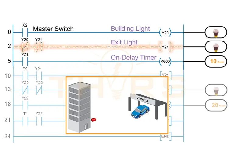
Ladder Diagram Is Ideal for Discrete Control Applications
PLC systems often control on/off devices like motors, valves, sensors, and relays. Ladder Diagram is particularly well suited for this type of discrete control.
Operations such as these are straightforward to design and visualize using ladder diagrams:
- Start/stop control
- Interlocking
- Safety logic
- Sequential operations
Clear and Visual Logic Flow in PLC Ladder Diagram
Ladder diagrams represent program flow from left to right, similar to the way electrical current flows in a control circuit. This visual structure helps users quickly understand how inputs affect outputs.
Each rung performs a specific task, making programs:
- Organized
- Easy to read
- Easy to modify or expand
This structured format improves clarity, especially in larger control systems.
Reliable and Deterministic Operation of Ladder Diagram Programs
PLCs execute Ladder Diagram programs using a predictable scan cycle. This ensures consistent and repeatable behavior, which is critical in industrial automation where timing and safety are essential.
Because PLC Ladder Diagram is structured and visually explicit, it reduces programming errors and supports stable system performance.
Ladder Diagram and Industrial Safety Standards
Many safety PLCs and safety-related control systems use Ladder Diagram due to its clarity and traceability. Its visual logic makes programs easier to review, validate, and certify in accordance with industrial safety standards.
This is especially important for applications involving emergency stops, machine guarding, and interlocking systems.
Ladder Diagram in Modern Automation
Even in modern automation, Ladder Diagram remains highly relevant. It integrates well with:
- HMIs
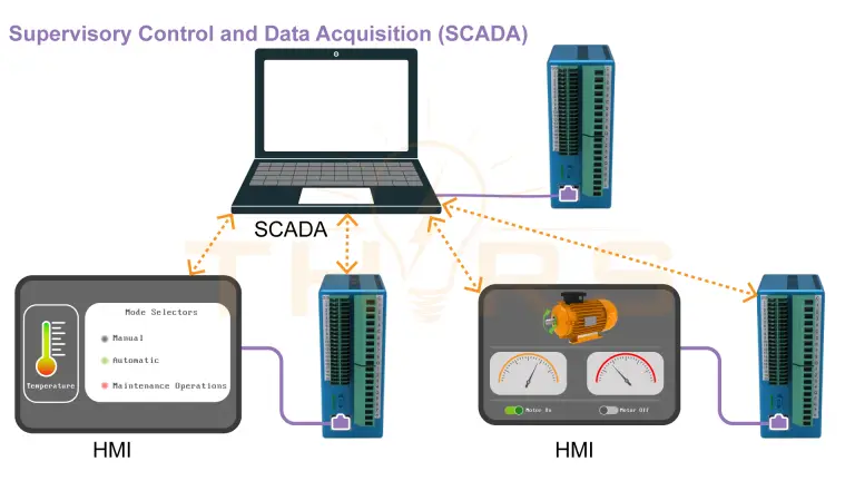
- SCADA systems that integrate with PLC Ladder Diagram
- Industrial communication networks
- Advanced PLC architectures
Many modern PLCs allow Ladder Diagram to be used alongside Structured Text and Function Block programming within the same project.
Conclusion
PLC Ladder Diagram remains one of the most practical and widely used programming languages for PLC systems. Its visual structure, reliability, and ease of maintenance make it well suited for industrial automation applications.
By closely reflecting electrical control logic, Ladder Diagram provides clarity and consistency in environments where safety, uptime, and predictable operation are critical. For both beginners and experienced professionals, it continues to be a dependable and industry-proven PLC programming language.
Are you interested in learning more about PLC programming? The THORS Programmable Logic Controller (PLC) Programming course would be a good place to start.