Understanding welding symbols and drawings is crucial in achieving high-quality and safe welds, contributing to the overall success of any type of welding project across various industries, including construction and manufacturing. Ensuring superior weld quality and adherence to stringent safety standards is important to avoid structural failures, operational downtime, and costly rework. Engineering drawings play a vital role in guiding welders with precise information for accuracy and clarity in performing each weld. These drawings provide essential information on weld dimensions, configurations, and specifications, which directly impact the overall integrity and performance of the welded structures.
The Role of Engineering Drawings in Reliable and Compliant Welding
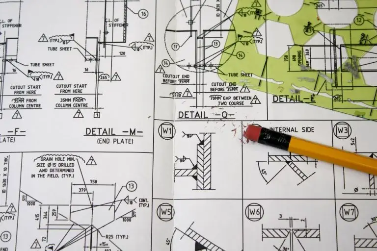
Engineering drawings for welding serve as a detailed guide for welders, providing information on how to perform welds accurately and efficiently. These drawings include standard welding symbols that specify the type and location of welds, ensuring consistency and compliance with industry standards. They also outline material specifications that help welders pick the right metals and alloys as per the drawing. Precise weld measurements and weld tolerances guarantee proper fit and alignment in the final assembly. They provide clear instructions on joint configurations by defining the joint preparation and fusion requirements that maximize structural strength. Engineering drawings for welding also provide guidelines related to inspection and quality control ensuring welds meet safety and regulatory requirements. A well-prepared engineering drawing serves as a universal language that eliminates misinterpretation among engineers, welders, inspectors, and fabricators.
By providing clear, well-structured instructions, these drawings enhance the reliability, durability, and efficiency of welded structures, ensuring they perform optimally over time. These drawings serve as a foundation for maintaining consistency in fabrication, reducing the chance of errors that could compromise structural integrity. Engineering drawings improve weld quality by:
- Enhancing reliability and durability with clear instructions that minimizes defects and inconsistencies, ensuring that welded structures maintain long-term performance.
- Defining proper joint designs, material specifications, and welding parameters, engineering drawings help achieve high-strength welds that withstand operational stresses.
- Eliminating confusion among stakeholders with standardized welding symbols and annotations that prevents misinterpretation between engineers, welders, and quality control teams. With clear and precise instructions, everyone involved in the welding process understands the exact requirements, leading to better coordination and fewer mistakes.
- Improving efficiency and reducing costs with detailed step-by-step welding instructions. These instructions minimize material wastage and rework, allowing fabrication processes to run smoothly. This not only enhances productivity but also makes the manufacturing process more cost-effective by reducing unnecessary delays and errors.
- Ensuring compliance with industry standards and regulatory requirements. Proper documentation ensures that welding projects adhere to recognized standards such as AWS, ISO, and ASME, guaranteeing that welds meet the necessary strength, safety, and performance benchmarks. Following these guidelines ensures that welds pass inspections and perform reliably across different applications and industries.
Accurate engineering drawings are the foundation of high-quality welding and safe structures. A well-prepared engineering drawing serves as a universal language that eliminates misinterpretation among engineers, welders, inspectors, and fabricators. Standardized symbols and notations ensure that everyone involved in the welding process understands the specific requirements, leading to consistent fabrication quality across projects and industries. Companies that prioritize well-prepared welding drawings not only improve efficiency but also enhance workplace safety and compliance. By following engineering blueprints meticulously, the risk of weld failure can be significantly reduced, leading to stronger and more reliable structures.
Need to brush up on welding terms and symbols? Watch our course introduction video below for a preview of what you will see in the THORS course, Engineering Drawings for Welding.