Electrical drawings bridge the gap between conceptual design and the practical implementation of electrical circuits. These drawings communicate a system’s intent long before any cables are laid or equipment is installed. However, the ability to accurately read and interpret electrical drawings is often underestimated, especially among early-career engineers. Reading electrical drawings is not just a supporting skill; it is an essential part of professional competence for electrical engineers.
The Universal Language of Engineering
Engineering drawings serve as a universal communication medium across engineering disciplines. In electrical engineering, they illustrate how energy is generated, transmitted, distributed, and controlled. Well-prepared drawings convey complex circuit relationships, equipment connections, and protection schemes far more effectively than verbal explanations or written text alone.
Electrical engineers must be proficient in reading various types of drawings, such as Single Line Diagrams (SLDs), schematic diagrams, wiring diagrams, layout drawings, and circuit control diagrams. Mastery of this visual language ensures smooth coordination between design, installation, and maintenance teams, reducing ambiguity and preventing project delays.
From Design Concept to Operational Reality
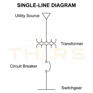
Electrical drawings serve as blueprints for entire electrical systems. They translate theoretical calculations into practical design elements and specify component ratings, conductor sizes, and protection devices. For example, an SLD presents the complete power distribution network on a single page, showing how power flows through transformers, circuit breakers, and switchgear.
When engineers understand these drawings, they can verify the logical sequence of operations, identify design flaws early, and ensure that on-site installations align with the original design intent. The ability to interpret drawings converts abstract ideas into safe, functional systems.
Maintaining Safety and Compliance
One of the most critical reasons for mastering electrical drawings is maintaining electrical safety. Drawings provide essential information about circuit protection, grounding arrangements, and isolation mechanisms. Misinterpreting this information can lead to hazards such as short circuits, equipment damage, arc flash incidents, or personal injury.
A proper understanding of electrical drawings enables engineers to verify compliance with standards such as the National Electrical Code (NEC). the International Electrotechnical Commission (IEC) 60364, and the Indian Standard (IS) 732. This ensures that every step in design, installation, and inspection adheres to established electrical safety practices applicable to the project’s location.
A Tool for Troubleshooting and Maintenance
Electrical drawings are also indispensable for troubleshooting electrical systems. Schematic and wiring diagrams support systematic fault tracing and help engineers locate open circuits, incorrect connections, or malfunctioning relays. In industrial and utility environments, where downtime is costly, the ability to quickly interpret diagrams enables faster, more accurate fault isolation and system restoration.
Additionally, as-built drawings serve as valuable references for future modifications or expansions, making them crucial assets in long-term facility management.
Building Competence
Developing electrical drawing interpretation skills begins with consistent practice. Engineers can start by:
- Studying standard electrical symbols
- Reviewing single-line and schematic diagrams from real-world projects
- Practicing wiring and termination layouts using CAD tools
- Comparing design drawings with as-built documents to understand field-level changes
In today’s engineering environment – where precision, safety, and efficiency are essential – the ability to read electrical drawings is not optional. Drawings capture the logic, functionality, and safety of every electrical system. Engineers who master this skill improve project accuracy and elevate their professional value in a competitive field.
Ultimately, engineers who can confidently read drawings are better positioned to lead projects, bridging the gap between design vision and operational success.
Are you interested in learning more about the engineering drawing for electrical circuits? The THORS Engineering Drawing for Electrical Circuits course would be a good place to start.