


Training
Entertainment in Education is the Future
Prepare to embark on an extraordinary adventure as we dive into the captivating world of the future of education. We will unravel the seamless integration

Gears
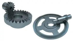
Spur Gears versus Helical Gears
Gear types can be classified according to the relative position of their axes of revolution. For example, there are gears for parallel shafts, gears for intersecting
Gears
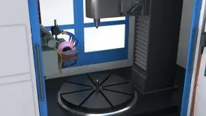
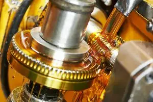
Gear Hobbing Cutting Parameters to Optimize the Hobbing Process
What are the Primary Gear Hobbing Cutting Parameters? Primary gear hobbing cutting parameters include the radial feed rate, the axial feed rate, the work spindle