


Career Planning
The Essential Skills of Modern Purchasing Professionals
In my professional career that spans more than three decades, I have had the privilege of working closely with purchasing. I can attest to the
Engineering Drawings
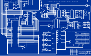
Reading Electrical Drawings: Why This Skill Is Essential for Electrical Engineers
Electrical drawings bridge the gap between conceptual design and the practical implementation of electrical circuits. These drawings communicate a system’s intent long before any cables
Engineering Drawings
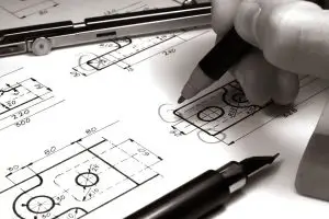
6 Mistakes to Avoid in Geometric Dimensioning and Tolerancing
Every manufacturing company that uses drawings to develop a manufacturing plan and estimate the production time might calculate product costs incorrectly if there are errors in those