

Engineering Drawings
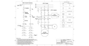
Reading Electrical Drawings: Why This Skill Is Essential for Electrical Engineers
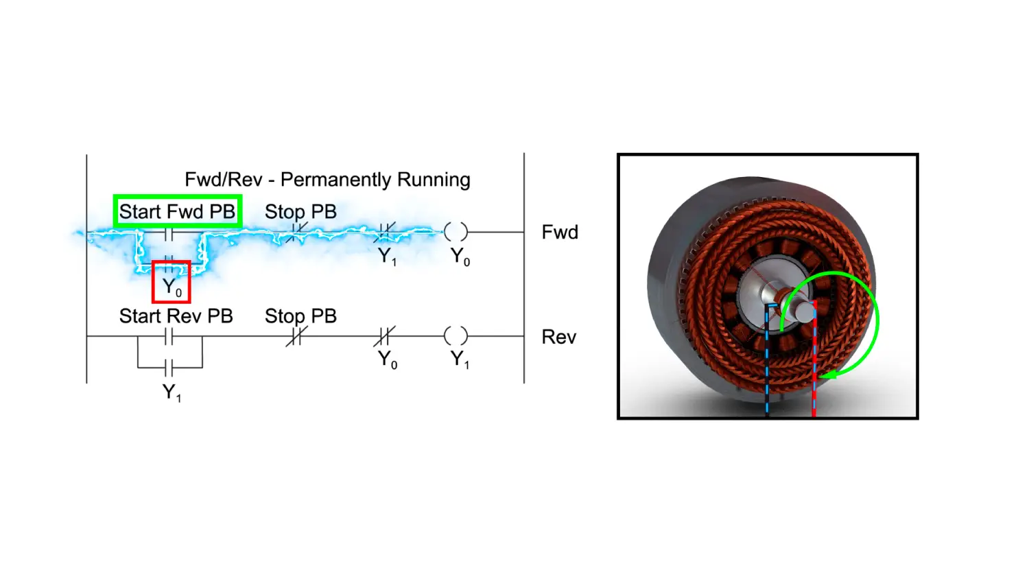
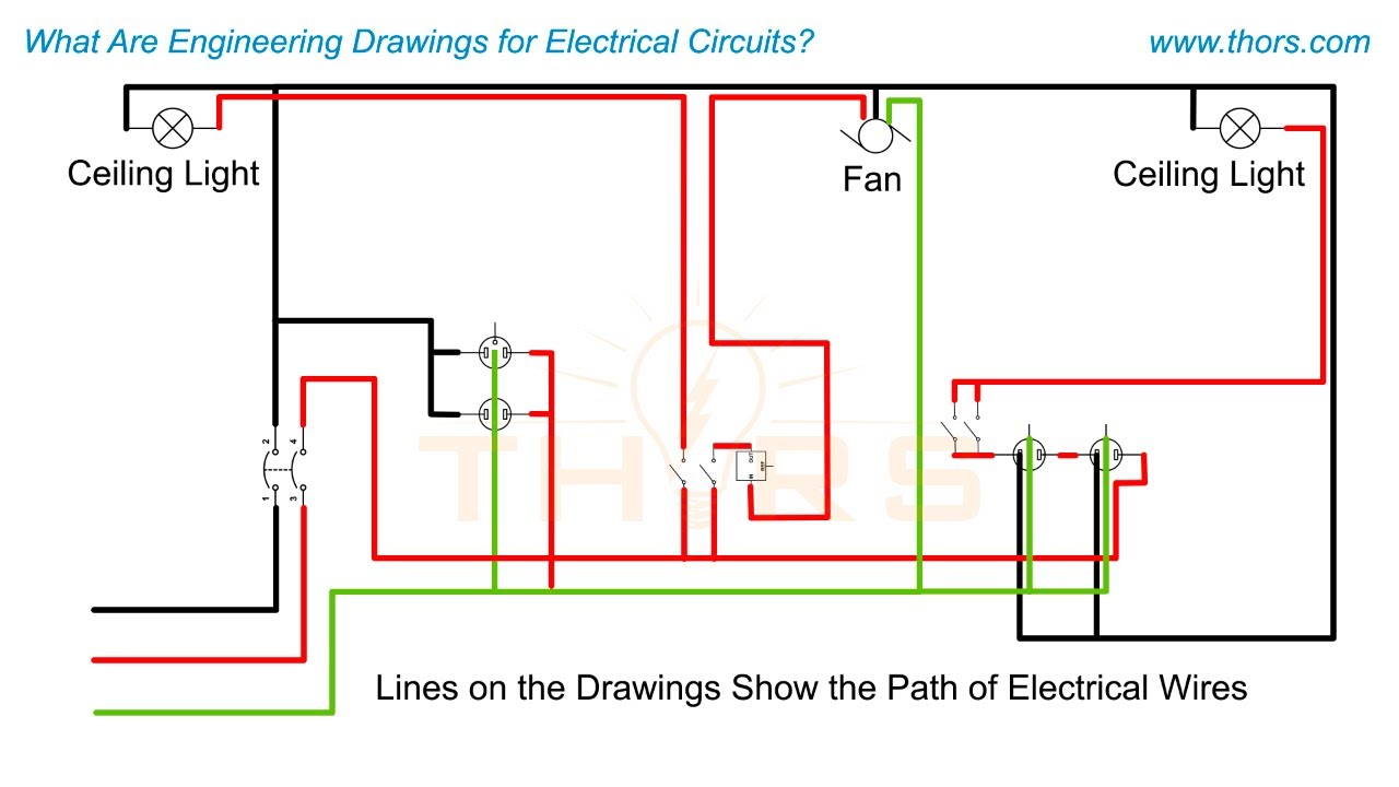
Electrical drawings bridge the gap between conceptual design and the practical implementation of electrical circuits. These drawings communicate a system’s intent long before any cables

Training
Is Your Issue a Skills Gap or a Knowledge Gap?
You may have received a call to action to address the skills gap, which might feel making a bridge across the Grand Canyon with a
Engineering Drawings
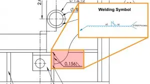
6 Mistakes to Avoid in Geometric Dimensioning and Tolerancing
Every manufacturing company that uses drawings to develop a manufacturing plan and estimate the production time might calculate product costs incorrectly if there are errors in those