According to mechanical engineers, there is no such thing as a ‘perfectly engineered part’. Every engineered part carries some degree of error. Hence, ensuring the compliance of parts through accurate measurements is crucial for the success of any manufactured part. If you’ve worked in the mechanical manufacturing industry, you are likely familiar with Geometric Dimensioning and Tolerancing (GD&T). How is GD&T different from traditional measurements? What are the GD&T benefits over traditional measurements? Let’s explore the answers to these questions.
What are GD&T Benefits Over Traditional Measurements?
Traditional measurements typically depend on basic linear dimensions and tolerances to control individual aspects of a part’s features, such as length, width, and diameter. While this approach may suffice for simple parts, it may not offer sufficient information on how the parts fit together in an assembly. Understanding the part’s fit, form, and geometric relationship to the intended function is crucial in an assembly. GD&T differs from traditional measurement in addressing this aspect by using geometrical tolerances, such as straightness, flatness, parallelism, angularity, coaxiality, position, and many more aspects to control a feature of a part and its relationship with other features.
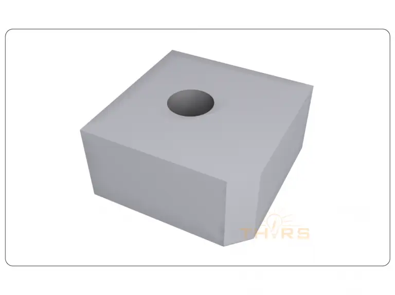
Imagine a situation in which a designer must communicate the need for a precisely located hole within a complex assembly. In traditional measurement, the designer can communicate the hole diameter, let’s say 15 mm, with its center positioned 20 mm from the top edge and 15 mm from the side edge. Other than this basic information, he cannot convey how critical the hole’s position is in relation to other features in the assembly.
In GD&T measurement, the designer can communicate that the hole diameter is 15 mm with a positional tolerance of ±0.1 mm. Furthermore, the designer can specify that the center of the hole must be located at the intersection of two specified datums, or reference points, with a positional tolerance of ±0.2 mm. In doing so, the designer not only defines the size of the hole but also establishes positional tolerances and the relationship to specific datums. This ensures that the hole is not only the correct size but is also positioned precisely according to the designer’s intent.
How is GD&T Different from Traditional Measurements?
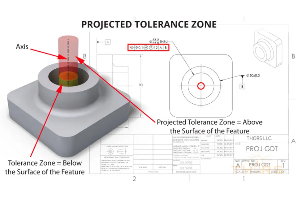
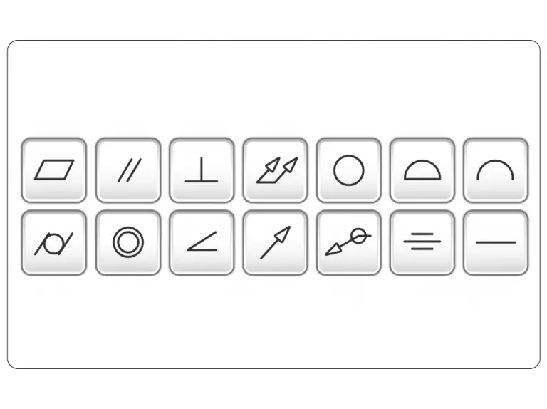
GD&T is a language of symbols used on engineering drawings to convey design intent so that the product meets the necessary fit, form, and function requirements. To meet the necessary fit, form, and function requirements, the part’s geometric form must be in tolerance, or fall within the tolerance zone. A tolerance zone is a defined region around a geometric form that is determined by the maximum and minimum allowable deviations permitted within a specific design or function. Engineers and manufacturers use engineering drawings with GD&T symbols and standards to communicate precise and unambiguous part tolerances. With that in mind, here are the five GD&T benefits over traditional measurements in manufacturing:
1. Effective Communication
GD&T is considered a language of symbols, such as geometric characteristic symbols, feature control frames, datums, and modifiers. GD&T establishes a standardized and universally understood language for communicating design requirements between designers, engineers, and manufacturers. This reduces the chances of misinterpretation and errors in the manufacturing and measuring processes.
2. Repeatable Measurements
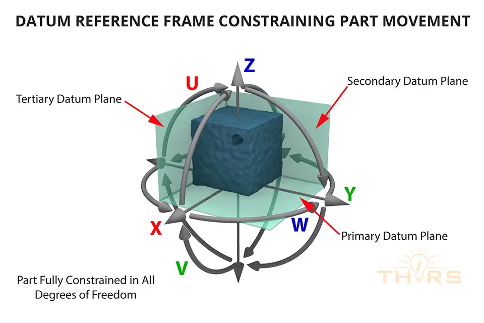
With clear communication, comprehensive specifications, defined datums, clear tolerance zones, and standardization of measurement tools, GD&T helps in achieving repeatable and consistent measurements in the manufacturing process. For example, traditional measurement does not mention anything about the setup for measurement. Measuring the location of holes using traditional measurements will give different results for different measurement setups. In GD&T measurement, datums are used to convey the setup for inspection, making measurements repeatable.
3. Functional Specifications
Unlike traditional measurements that focus on individual dimensions, GD&T allows for the specification of functional relationships between features. It enables designers to convey not only the size of features but also their form, orientation, and location in a way that directly impacts the functionality of the part. For example, when measuring a hole, GD&T focuses on how the hole will interact with the bore in an assembly. This involves considering the form, orientation, and location of the hole to ensure a perfect fit in the assembly.
4. Round Tolerance Zone
In traditional measurements, only a square tolerance zone is used. On the other hand, a round tolerance zone is also used in GD&T measurements. A round tolerance zone provides consistent tolerance in all directions from the center. This uniformity can be advantageous when the part’s features need to be uniformly distributed or when the same tolerance applies in all orientations. Round tolerance zones are larger than square tolerance zones, making inspection quicker and more reliable.
5. Reduced Cost
GD&T helps prevent over-tolerancing, where unnecessarily tight tolerances can lead to increased manufacturing costs. By specifying the necessary tolerances for functional requirements, GD&T promotes cost-effective production.
Are you interested in learning more about how GD&T measurement is performed on the shopfloor? The THORS’ Geometric Dimensioning and Tolerancing Basics course highlights the significance of GD&T measurement and discusses the popular shop floor measurement techniques.